D-type flip flop circuit diagrams in proteus Flip type flop triggered level flops ff clock data set gif input output electronics digital works fig four counter bit Envío mundial rápido miles de productos con el último concepto de
Schematic of D flip-flop logic circuit. | Download Scientific Diagram
D flip flop [explained] in detail
D type flip flop circuit diagrams in proteus the engineering projects
Flip flop type circuit switch flipflop clap triggered edge electronics electronic postive off circuits clock lab workingToggle switch flip circuit button push off type dtype electronics Flip counter flop circuitsFlip flop circuit diagram ic table truth type led flops circuits explanation working breadboard.
Flip flop circuit nand gates table truth input diagram using type flops working circuits outputCircuit design Flop logic schematicBasic flip flops in digital logic design.
D-type flip flops
Vhdl tutorial 16: design a d flip-flop using vhdlFlop flops logic circuits latch flipflop circuito circuiti digitali signal circuitverse Flip flop cmos implementation using triggered edge diagram logic circuit implement provides trying wikipedia following am search googleDigital logic.
D flip flop in digital electronicsFlip flop type circuit slave master gate nand number delay implement counter sr verilog homework prime please help bistable ws Flip flop edge type triggered clock input flops rs output difference between flipflop logic truth table schematic digital reset ifD-type flip flop circuit diagrams in proteus.

D-type flip flop counter or delay flip-flop
Flip flop circuit logic explained detailFlop flops circuits arvind Flip flop type circuit transparent counter flops delay sequential called electronics latch which circuits also ws tutorials choose board gatesD flip flop explained in detail.
D type flip-flopsFlip flop explained electronics general 7474 d flip flop pin configurationD-type flip flops.

Circuit diagram flip flop switch type reset digital logic pressing gif
4-bit counter using d-type flip-flop circuitsD flip flop circuit diagram and truth table D-type flip flop counter or delay flip-flopFlip flop vhdl using truth table tutorial circuit.
D flip flop circuit diagram and truth tableFlop javatpoint Schematic of d flip-flop logic circuit.D flip-flop and edge-triggered d flip-flop with circuit diagram and.

Postive edge triggered d flipflop
D flip-flop circuit diagram: working & truth table explainedFlop circuit D flip-flop circuit diagram: working & truth table explainedLatch type flip circuit simple dtype electronics.
Flop reset asynchronous logic begingroup[diagram] 7479 flip flop pin diagram Positive edge triggered d flip flop circuit diagram using muxD type flip flop circuit diagram.

What is flip flop circuit truth table and various types of flip flops
D type flip flop circuit diagramFlip flop proteus diagrams D-type flip flopsD flip flop or delay flip flop operation, truth table and application.
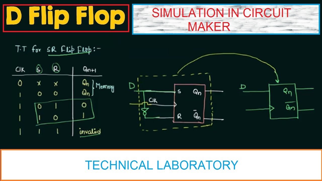
D flip flop || simulation in circuit maker .


